")
2LIN2CAN v5 Adapter
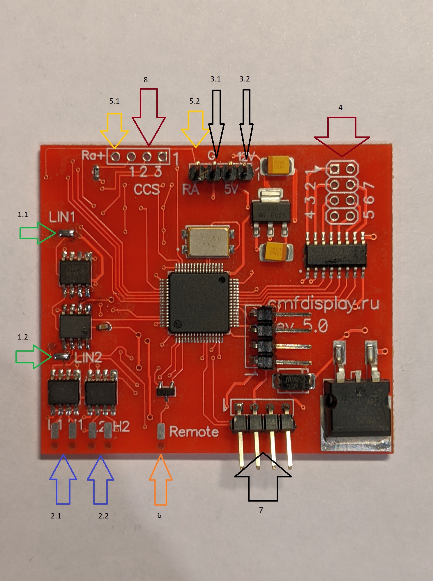
Description of the adapter outputs
1. Two LIN buses
1.1 LIN 1 is designed to control the steering wheel buttons, the adapter acts as a bus master
1.2 LINE 2 is designed to simulate steering wheel buttons, to transmit data to the standard control unit. the adapter acts as a slave device. This output is needed to implement the converter function of one LIN protocol to another (LIN2LIN mode)
2. Two CAN buses.
2.1 CAN1
2.2 CAN2
Both CAN buses can be configured to operate at 62.5 kbit/s, 100 kbit/s, 500 kbit/s. The CAN bus settings are made individually, regardless of each other
3. Adapter Power Supply
3.1 power supply minus (ground)
3.2 plus vehicle on-board power supply (12 V)
4. Outputs for load control with current up to 500 mA
The adapter has 7 universal outputs, individually configurable, the numbering of the outputs corresponds to the marking on the printed circuit board of the adapter
5 Resistive output 0-50 kOhm
5.1 Resistive output (RA) with programmable resistance in the range from 0 to 50 kOhm. Built on the basis of a digital potentiometer. For more information, see the adapter settings section
5.2 The additional output (RA+) has two states open (infinite resistance) and closed to ground (resistance 0 ohms). The load current through this output should not exceed 200 mA. It is used, for example, for resistive control of Pioneer radio recorders.
6. Digital output for radio control (NEC protocol)
It is used for a number of radio recorders controlled by the NEC protocol
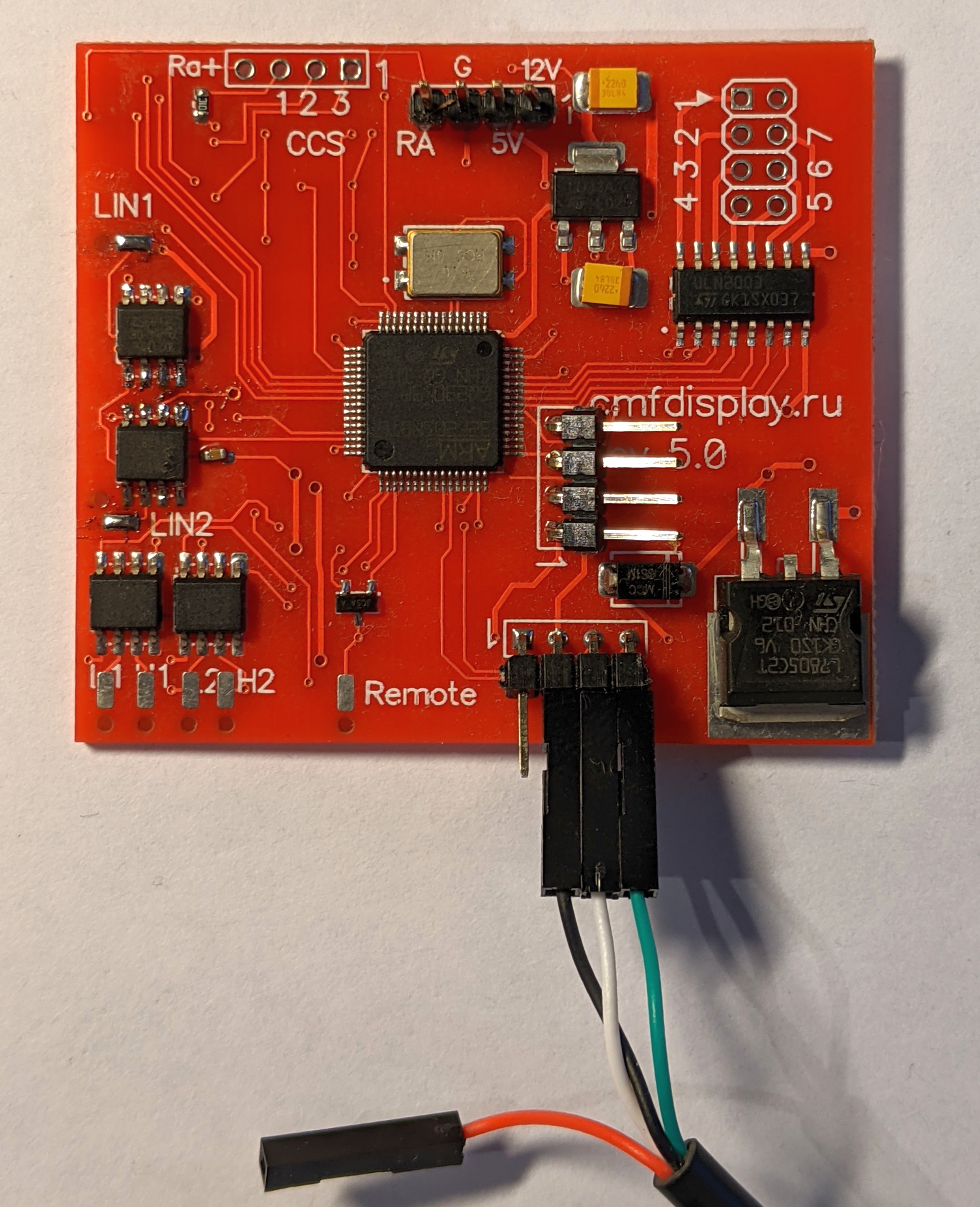
7 USB
it is designed to connect the cord with which the adapter is connected to the computer, the cord wires are connected according to Fig. 3. The red wire is not used, but it can be used to power the board in the technological mode "on the table", for firmware or adapter settings.
8. Cruise control outputs
Three outputs are designed to supply KK signals directly to the engine ECU
USB cord connection diagram